Contents
1. Define What the Layout Must Deliver
2. Compare Supports and Aiming Options
3. Calculate the Longest Useful Beam
4. Check Glare and Structural Consequences
1.Define What the Layout Must Deliver

Consider a baseball park where one foul boundary adjoins a road and the outfield fence is close to homes. A neat six-pole sketch may leave poor aiming options on that side. A larger stadium may instead offer high mounting positions along its stands. The site makes these arrangements different engineering problems, even when both proposals reach the same average lux.
A baseball lighting layout must cover the infield, outfield, foul territory, and useful space above the field. Engineers should establish field dimensions, competition requirements, likely ball paths, property limits, camera directions, and service access before choosing the support arrangement. The infield and outfield lighting guide explains why one average value is not a complete brief.
2.Compare Supports and Aiming Options
A multi-pole scheme uses separate masts around the field. A perimeter arrangement distributes luminaire groups along stadium structures or a larger set of perimeter positions. Here, “ring” describes distributed mounting positions; it does not mean a continuous luminous strip. Six and eight poles are examples to compare, not universal prescribed counts.
The table compares concept options. More mounting points can shorten some throws and provide additional directions, but they also add connections, aiming groups, and maintenance locations. A baseball pole-height review should accompany every option. A low perimeter mounting line can still create shallow beams and expose bright sources to players.
3.Calculate the Longest Useful Beam
Pole height and setback define the downward aiming geometry. For a target on a horizontal plane, the vertical drop Δh equals the horizontal distance d multiplied by tan θ, where θ is the downward angle below horizontal. A 60 m throw at 25° needs about 28 m of vertical drop. This is a geometry example, not a universal mast-height rule.
Little League’s 2025 guide sets application-specific minimum aiming angles of 25° for specified infield directions and 21° for specified cross-outfield directions. Designers must read the associated location drawings. A professional stadium needs its own approved brief. Engineers should also calculate beams through relevant elevated planes, because a uniform ground grid does not establish continuous illumination of a flying ball.

4.Check Glare and Structural Consequences
Each mounting position changes the sources visible from home plate, the mound, and the outfield. Cross-light can improve coverage, but a source behind the ball may lower visual contrast. The GR background guide introduces glare assessment. CIE 112 has limits for viewing directions, so upward ball tracking also requires a separate sightline review.
The structure follows the selected optical arrangement. More fixtures on fewer masts concentrate mass and effective projected area, or EPA. A perimeter scheme distributes that load but requires verified roof or stand capacity. The high-mast structural guide connects fixture loading, wind exposure, and foundations. Engineers must include brackets, cables, maintenance access, and future equipment in the review.
5.Compare Models and Verify the Installation
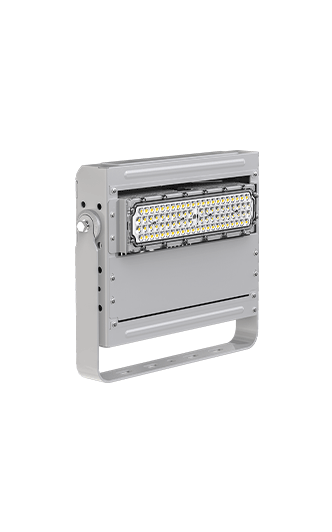
Engineers should model both options using the exact IES or LDT file, final coordinates, beam selections, and maintenance factor. They should compare maintained illuminance, uniformity, aerial coverage, player views, spill light, and power. The CPS Dubhe 1000W light offers modular optics and an optional anti-glare hood; those options need model-specific photometric confirmation.
CPS reports four 18 m lifting poles and average illuminance above 550 lx in a Grade III football high-pole project. This is football evidence, not proof that the same geometry suits baseball. The transferable process is to match mounting positions and optics, commission aiming, and retain measurements.
At handover, the team should verify coordinates, angles, scenes, and approved measurement planes. A baseball field pole layout earns its place through the complete comparison, rather than pole count alone. Operators should retain the aiming schedule and recheck the design when fences, stands, or mounting positions change.