Contents
1.Check the Aim Before Adding Power
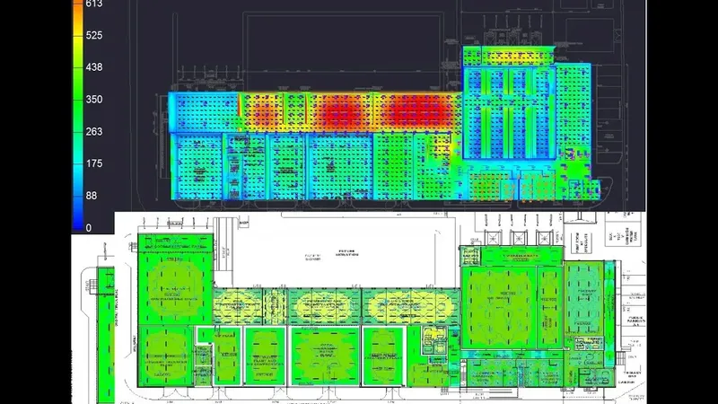
Floodlight aiming controls where each luminaire sends its intensity. A small rotation can move useful light away from a weak zone and into an already bright area. The result can be a hot spot beside a darker patch, even when fixture count and power remain unchanged.
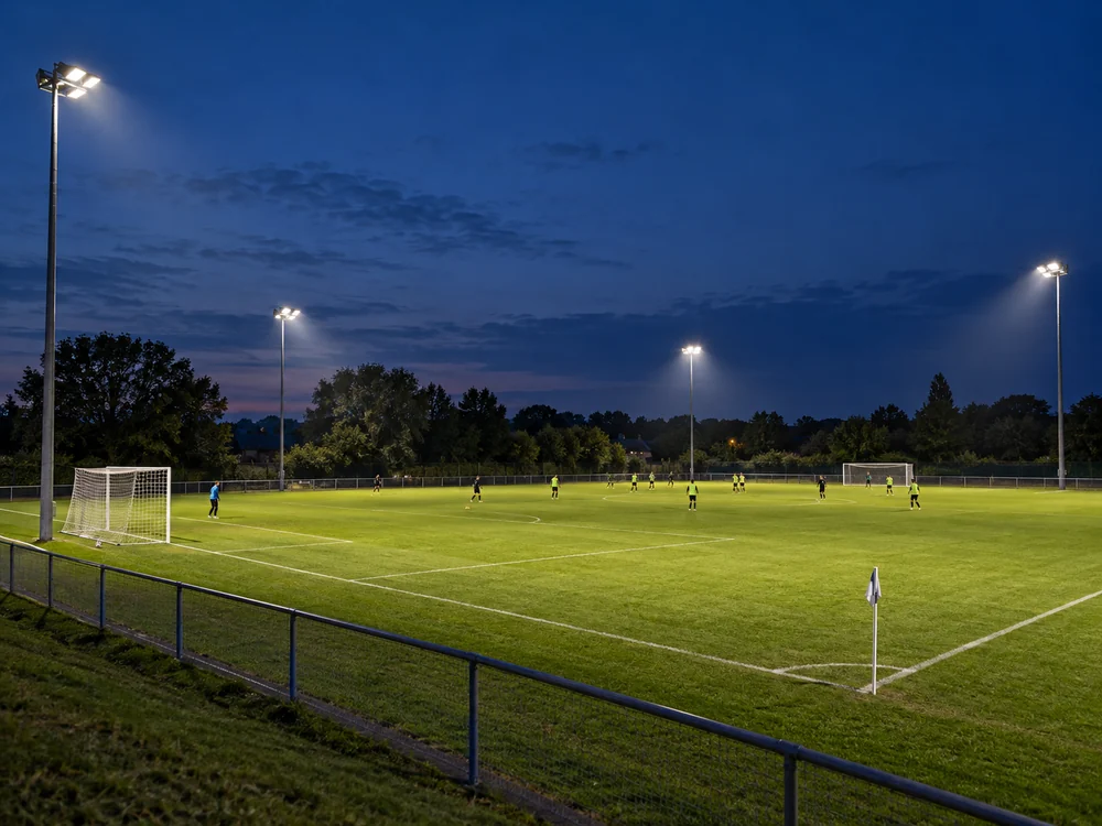
An illustrative handover problem starts with the correct luminaires installed on the correct poles. The average lux looks acceptable, but one touchline is uneven. Before adding power, the engineer checks optic codes, aiming coordinates, control scenes, and measurements. A bracket that looks close to the drawing may still point at a different target.
2.Small Angles Can Move the Target
That target shift can be estimated before running a full model. For an ideal optical axis meeting level ground, x = h × tan α. Here h is mounting height above the ground and α is the axis angle from downward vertical. This is a ground-intercept calculation, not a lux calculation or a universal software tilt convention.
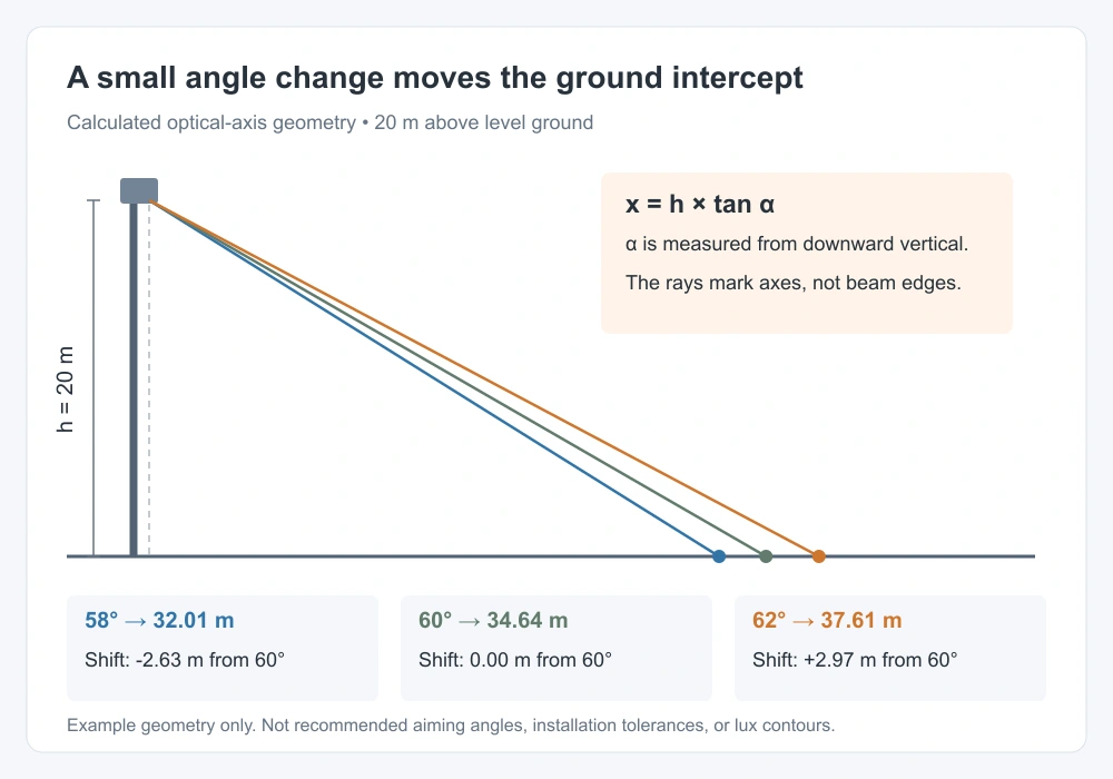
At an illustrative 20 m height, changing α from 60° to 62° moves the intercept about 2.97 m farther away. Changing it to 58° moves it about 2.63 m nearer. The table gives the three positions. These values are not recommended pole heights, aiming limits, or installation tolerances. An asymmetric optic’s intensity peak may not align with its housing reference.
Calculated example: 20 m above level ground. The angle is measured from downward vertical; displacement is relative to 60°. Swipe sideways on a narrow screen.
3.Shifted Beams Change the Overlap
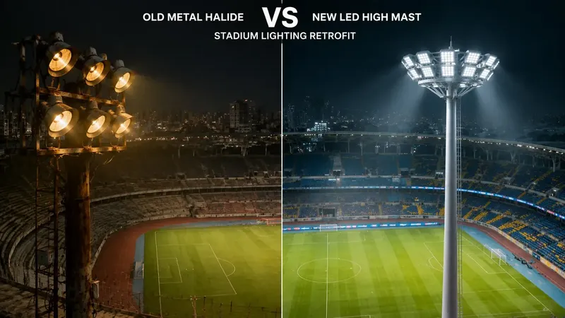
That movement matters because a layout depends on contributions from several directions. A misplaced beam can reinforce a bright zone while withdrawing light from an edge. Narrow distributions and long throws can be sensitive to such changes. The CPS discussion of light distribution in LED retrofits explains why the selected optics must match the layout.
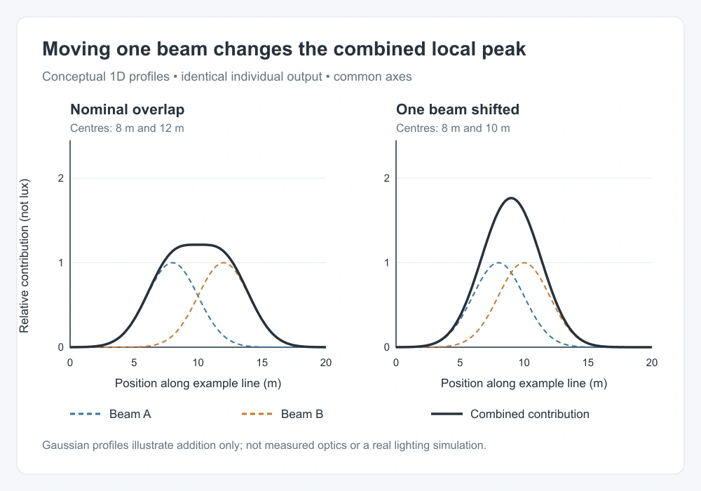
The change in illuminance follows both direction and geometry. The IES relationship E = I × cos γ ÷ d² uses intensity I toward each point, distance d, and incidence angle γ. Rotating the fixture changes which part of the candela distribution serves that point. The designer must also recheck vertical light, shadows, and glare from player positions; a hot spot alone does not describe every risk.
4.Test Aiming Errors in the Model
Those effects need a repeatable aiming sensitivity check. Begin with verified IES/LDT files and the approved positions, heights, shielding, calculation planes, and scenes. The CPS DIALux and AGi32 simulation guide introduces this workflow. Change one aiming group first, while keeping every other input fixed, then test plausible combined installation deviations.
Compare the same grid, maintained-light assumptions, isolux scale, minimum and average illuminance, and explicitly defined uniformity ratios. Include relevant vertical planes and boundary receptors. AGi32 warns that photometric-file orientation can differ between laboratories. Record the angle origin, sign, and rotation order. A sensitivity test should establish project-specific margins; an arbitrary ±2° test is not an acceptance standard.
5.Check the Bracket and Commissioning Record
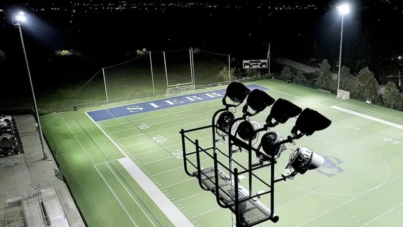
The model’s angles must then become reliable mechanical settings. CPS describes an adjustable mounting platform for the Dubhe Projection Light 1000W; the actual unit still needs its approved reference surfaces and installation instructions. A digital inclinometer measures a housing surface, not the optical axis by itself. Check orientation and target coordinates as well as inclination.
The published GameFlood installation instructions warn that inadequate bolt tightening can allow wind vibration to cause loss of aim. Their torque values apply to that product, not to CPS fixtures. Installers must use the relevant manufacturer’s method, suitable access equipment, and safe isolation procedures. CIE 150:2017 provides obtrusive-light guidance, so boundary checks remain part of acceptance after re-aiming.
6.Connect the Aim to Project Evidence
Project evidence shows the scale of that task. CPS describes its CRRC Zhuzhou football lighting retrofit as a four-corner arrangement using 25 m high masts. This supports discussing long-throw optical coordination. The published page does not provide a controlled aiming-error test, so it cannot establish a percentage improvement from correcting a two-degree error.
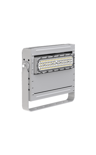
A replacement such as the Polaris TS-BJX modular floodlight also needs configuration-specific photometry and a fresh aiming check. The handover should retain fixture IDs, file versions, target coordinates, angle settings, fastening records, operating scenes, and calibrated measurement results. Stable sports lighting uniformity comes from the verified installed layout, not from wattage or bracket marks alone.
7.Technical Sources
Keywords: floodlight aiming, floodlight aiming angle, aiming errors, LED sports lighting, hot spots, beam overlap, sports lighting uniformity, photometric simulation, IES files, LDT files, aiming sensitivity, lighting commissioning, glare control, spill light.