Contents
1.Start With the Coverage Target
A floodlight beam angle describes light spread, not a guaranteed number of square metres at the required lux. For a circular beam aimed straight down at level ground, geometry gives a useful first estimate. The final coverage still depends on mounting height, directional intensity, aiming, and contributions from other luminaires.
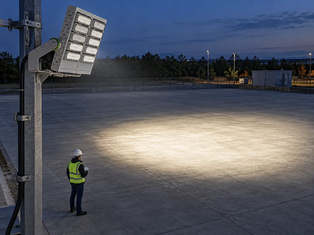
Consider a contractor comparing 30°, 60°, and 90° optics for the same yard. The wider option appears to need fewer fixtures, but its outer area may fall below the specified illuminance. The CPS floodlight product range is a starting point for that comparison. The design brief must define the task area, maintained lux, uniformity, and boundary conditions first.
2.Read the Beam Angle Correctly
The Illuminating Engineering Society defines beam angle using the directions where luminous intensity reaches 50% of its peak. Its field angle uses 10%. These limits describe intensity in candelas, not illuminance in lux. Manufacturers may use different conventions, so the buyer should confirm the stated threshold and the photometric report.
Those definitions also explain why one angle can be incomplete. A 30° × 70° distribution spreads differently across two planes. Asymmetric optics may place peak intensity away from the housing axis. The CPS discussion of retrofit light distribution gives useful layout context, but the exact IES or LDT file must identify the selected optic.
3.Estimate the Footprint, Not the Lux
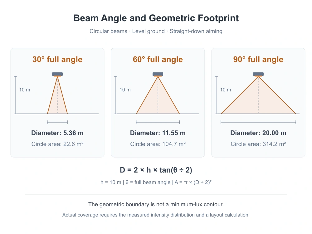
For an ideal circular beam, the geometric diameter is D = 2 × h × tan(θ ÷ 2), where h is the height above the receiving plane and θ is the full beam angle. The beam axis must be perpendicular to that plane. The circle area is A = π × (D ÷ 2)².
At an illustrative height of 10 m, a 60° beam gives a diameter of about 11.55 m. The table compares three ideal cones at that same height. These figures are calculations, not CPS test results or recommended pole heights. The listed area is not a minimum-lux contour and must not be used directly to set fixture spacing.
The comparison assumes a circular beam, 10 m height, level ground, and straight-down aiming. You can swipe the table sideways on a narrow screen.
4.Account for Aiming and Edge Losses
Real installations rarely preserve that simple circle. Tilting a floodlight can create an elongated footprint and increase distance to the far edge. A point-source estimate combines the inverse-square and cosine laws: E = I × cos γ ÷ d². Here I is intensity toward the point, d is source-to-point distance, and γ is the incidence angle measured from the surface normal.
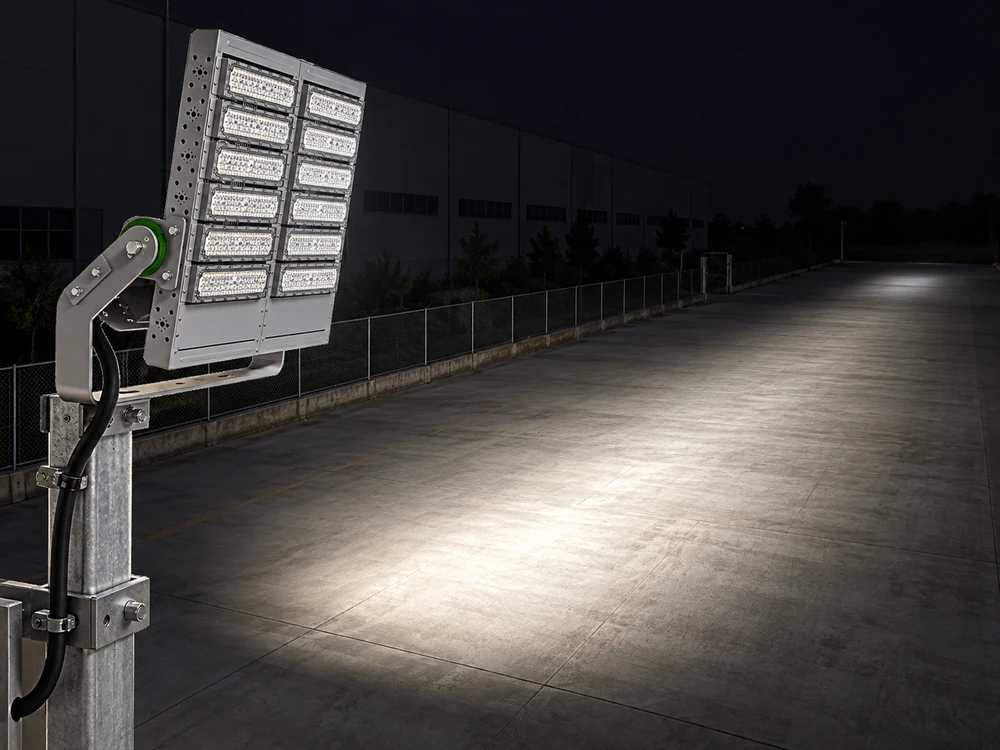
That relationship makes a 50%-intensity beam boundary different from a 50%-lux contour on the ground. A wider visible patch can still contain weak edges or strong hotspots. Engineers must assess overlap, vertical light, shadows, and player glare and sightlines alongside coverage. They should not assume that wider beams or more overlap always improve the result.
5.Check the Layout in a Photometric Model
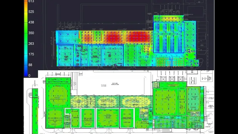
A photometric simulation should use the selected IES/LDT file, actual coordinates, mounting heights, orientation, tilt, and shielding configuration. The CPS DIALux and AGi32 guide introduces this workflow. Designers should also confirm how the file’s optical axes relate to the physical housing. AGi32 documentation warns that incorrect photometric orientation can invalidate the calculation.
The model should include the relevant calculation planes, obstructions, maintenance assumptions, and property receptors. DIALux supports horizontal, vertical, and camera-oriented illuminance, with configurable grids. The designer should compare numerical results and common-scale isolux plots rather than judge coverage from rendering brightness. Extra edge checks can help diagnose local problems without replacing the prescribed acceptance grid.
6.Connect the Model to Project Evidence
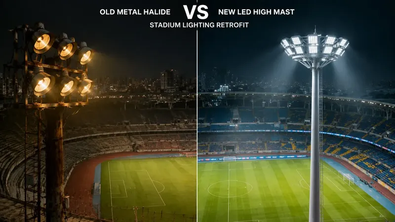
CPS describes a Grade III high-pole football project with four-corner placement and 18 m lifting poles. The company reports average illuminance above 550 lx after commissioning. That record illustrates coordinated layout and optical matching. It does not establish a universal beam angle or coverage area, and the page does not provide a complete independent point-by-point acceptance report.
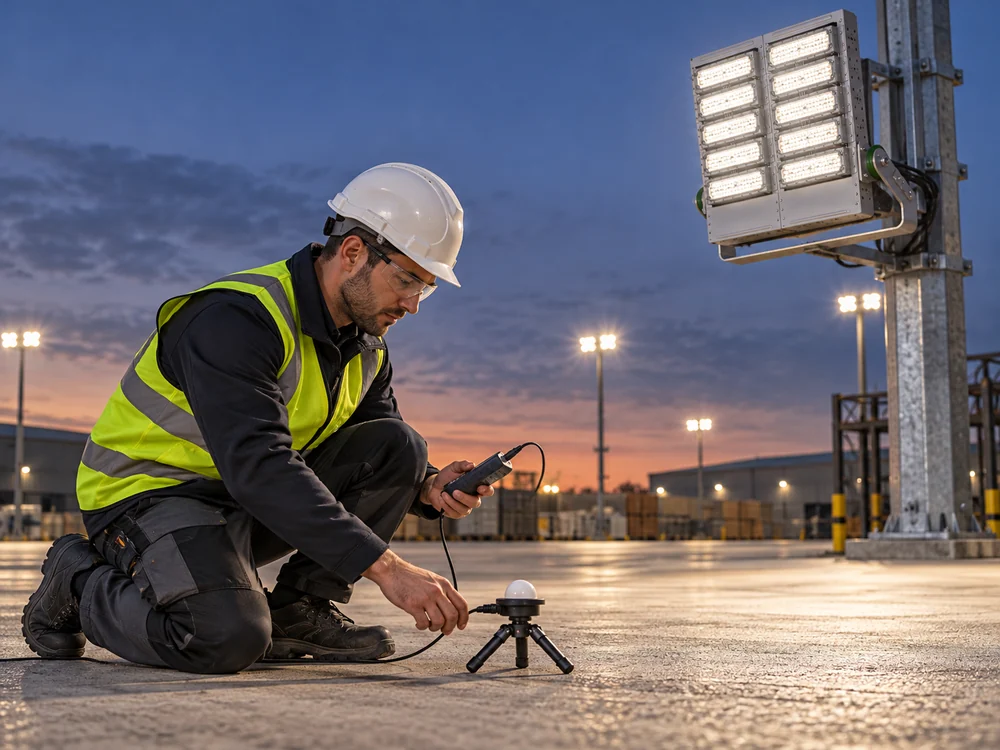
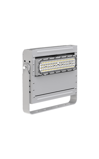
For a new project, a product such as the Dubhe Projection Light 1000W still needs a model-specific optical file and aiming schedule. Commissioning should compare calibrated lux readings with the approved planes, positions, operating scene, and installation settings. The useful floodlight coverage is the area that meets the brief after those checks, not simply the area that looks illuminated.
7.Technical Sources
Keywords: floodlight beam angle, floodlight coverage, LED floodlights, lighting layout, beam angle calculation, mounting height, floodlight aiming, IES photometric files, LDT files, DIALux simulation, illuminance uniformity.