Contents
1.Choose the Distribution for the Site
Symmetric floodlights distribute intensity evenly about an axis or one or more symmetry planes. Asymmetric floodlights redistribute it differently across directions, often to push light forward. Neither type is always better. Mounting positions, throw distance, useful light, and boundary conditions determine the stronger layout.

A four-corner court layout and a sideline-only scheme need different optical planning. Nearby homes also constrain aiming. A forward-throw optic may help reach distant zones without excessive housing tilt. Selected long throws may still suit narrow symmetric optics. The CPS guide to retrofit light distribution explains why existing pole geometry must enter this comparison.
2.Read the Optical Axes, Not Just the Beam Shape
That layout decision needs more detail than a beam-angle label. A symmetric distribution can be circular or elliptical. A 30° × 70° beam has different spreads in two planes, but those two numbers alone do not prove forward-throw asymmetry. A tilted symmetric floodlight can also create an elongated footprint on the ground.
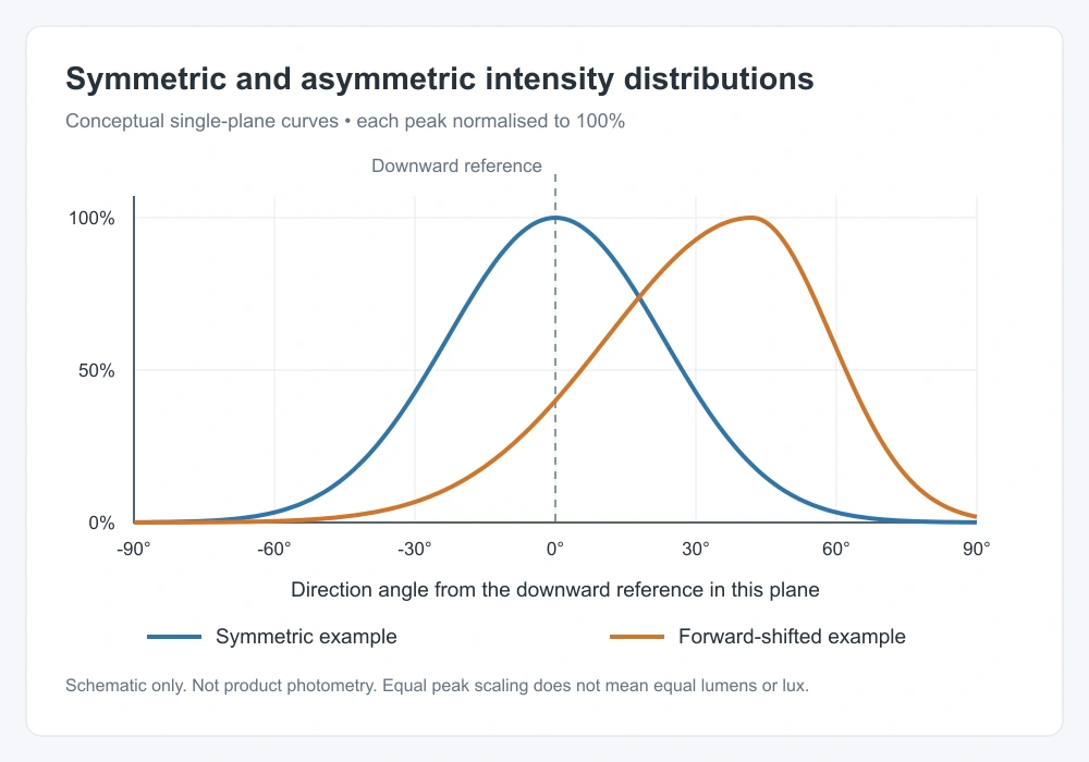
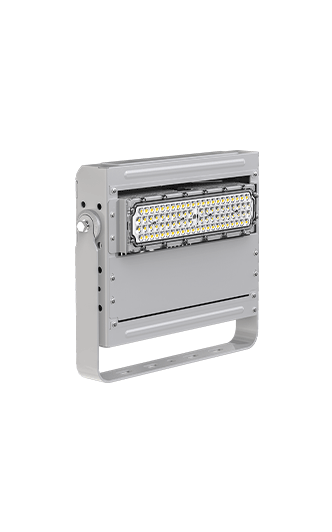
The designer should inspect the candela distribution, its symmetry planes, peak-intensity direction, and file orientation. SITECO’s published optics range separates symmetric elliptical and asymmetric distributions. CPS lists several optical options in its range, including the Dubhe Projection Light 1000W. Buyers should request the exact optic code and IES/LDT file rather than infer its distribution from a housing photograph.
3.Understand the Near-to-Far Lighting Loss
The intensity curve matters because distant ground points receive less illuminance even at equal candela. For a point source above level ground, E = I × cos γ ÷ d². The IES cosine-law definition supports this relationship. Here I is intensity toward the point, d is distance, and γ is measured from the ground normal.
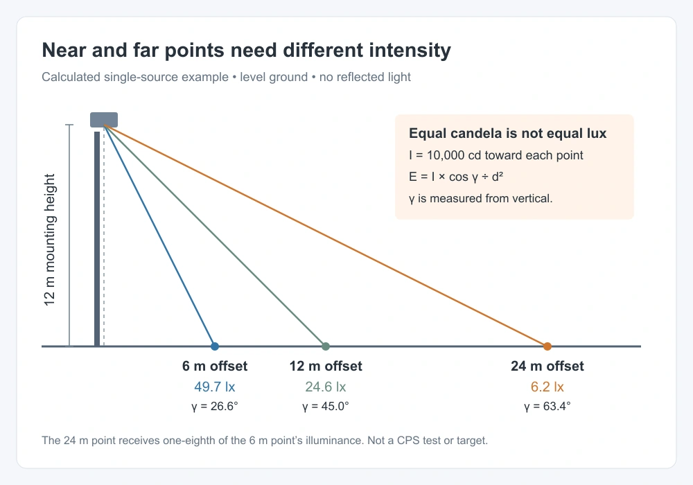
At 12 m height, the example below assumes 10,000 cd toward each point. The 24 m offset receives one-eighth of the illuminance at the 6 m offset. An asymmetric optic can allocate more intensity toward distant zones, but its actual curve must provide that balance. These calculations exclude other luminaires and reflected light. They are not CPS test results or recommended design targets.
Example only: 12 m mounting height, level ground, and 10,000 cd toward every point. The angle is measured from downward vertical. Swipe the table sideways on a narrow screen.
4.Balance Reach, Overlap, and Glare
That distance penalty explains the appeal of asymmetric forward throw at a site boundary. A suitable optic can reduce unnecessary backlight while serving the target area. Some designs achieve this with less physical tilt. The benefit depends on the tested distribution, installation angle, shielding, and orientation. Asymmetry alone does not guarantee zero upward light.
Symmetric narrow optics remain useful for selected long throws. Mixed distributions can serve near, middle, and far zones, but excessive overlap can create hot spots. Both options still need checks for vertical illuminance, shadows, and player glare and sightlines. CIE 150:2017 addresses obtrusive outdoor light. Its guidance does not make one optic automatically compliant.
5.Compare Both Options in the Same Model
Those trade-offs should be tested in a controlled photometric simulation. Start with the same site geometry, task planes, calculation grids, maintenance assumptions, and operating scene. The CPS DIALux and AGi32 guide introduces the modelling workflow. Use verified files for each optic, then optimise aiming within the same mounting and structural constraints.
AGi32 documentation warns that photometric-file orientation may differ between laboratories. Engineers must map the file axes to the actual luminaire and bracket. Compare maintained horizontal lux, required vertical planes, Emin/Eavg, the applicable glare method, boundary receptors, and input power. Use identical isolux scales and disclose any changes in fixture count or output. A brighter rendering is not performance evidence.
6.Verify the Selected Layout on Site
Model results also need a clear link to installed settings. CPS describes a Grade III football lighting project with four-corner placement and 18 m lifting poles. That published arrangement shows the importance of matching layout and mounting height. It does not establish a universal optic choice or prove that asymmetric optics outperformed symmetric ones in a controlled comparison.
For a new scheme, a platform such as the Polaris TS-BJX modular floodlight still needs configuration-specific photometry. Commissioning should confirm optic labels, coordinates, mounting heights, aiming angles, operating scenes, and calibrated measurements. Select symmetric or asymmetric floodlights on the layout’s verified results. Keep the approved calculation and as-built aiming schedule together so later replacements preserve the intended distribution.
7.Technical Sources
Keywords: symmetric vs asymmetric floodlights, floodlight light distribution, asymmetric optics, symmetric optics, LED sports lighting, candela distribution, forward throw, floodlight aiming, photometric simulation, IES files, LDT files, illuminance uniformity, glare control, spill light.