Contents
1. Start With the Event Visual Task
2. Uniformity, Illuminance, and Glare
3. Build the Lighting Layout by Zone
1.Start With the Event Visual Task
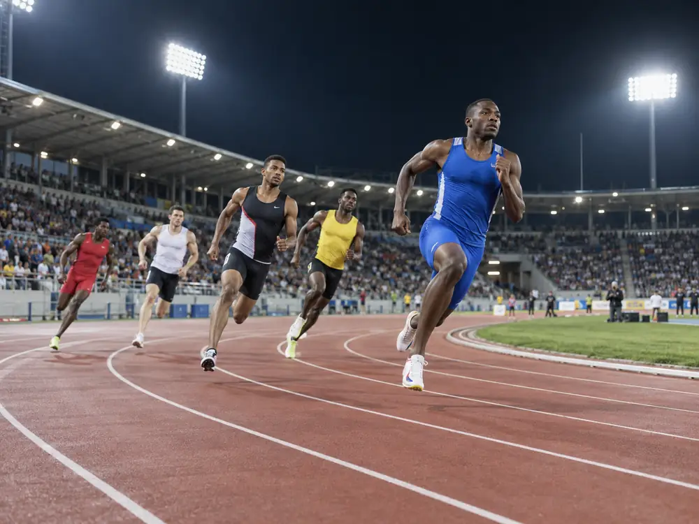
A 400 m track is not one flat rectangular task. Runners move through straights, bends, staggered starts, relay zones, hurdles, and a finish line. Light reaches each point from different mast distances and angles. A design can pass its average lux target while one outer lane or bend remains visibly darker.
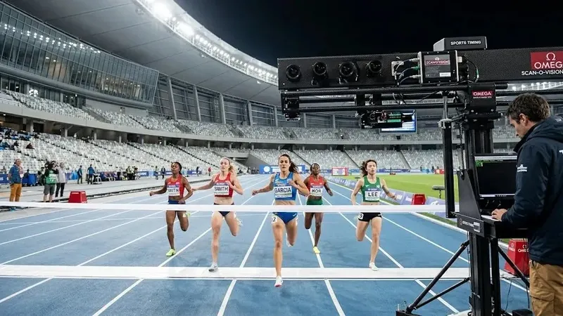
This is why track and field lighting uniformity starts with movement, viewing direction, and risk. The World Athletics facilities manual separates the needs of athletes, officials, spectators, television crews, and photographers. Faster competition increases the visual demand, so the design brief must state the event level and media requirements before fixture selection.
2.Uniformity, Illuminance, and Glare
Lighting engineers use uniformity ratios to expose these weak points. U1 = Emin / Eavg compares the darkest measured point with the average. U2 = Emin / Emax shows the total contrast range. The project specification must state which ratio it uses because some standards express the same relationship as average-to-minimum or maximum-to-minimum.
Horizontal illuminance, or Eh, supports lane marks and the ground plane. Vertical illuminance, or Ev, supports athletes, implements, officials, and cameras. The CPS guide to World Athletics lighting explains how these values work with glare and color requirements. The applicable contract standard must provide the final maintained targets.
3.Build the Lighting Layout by Zone
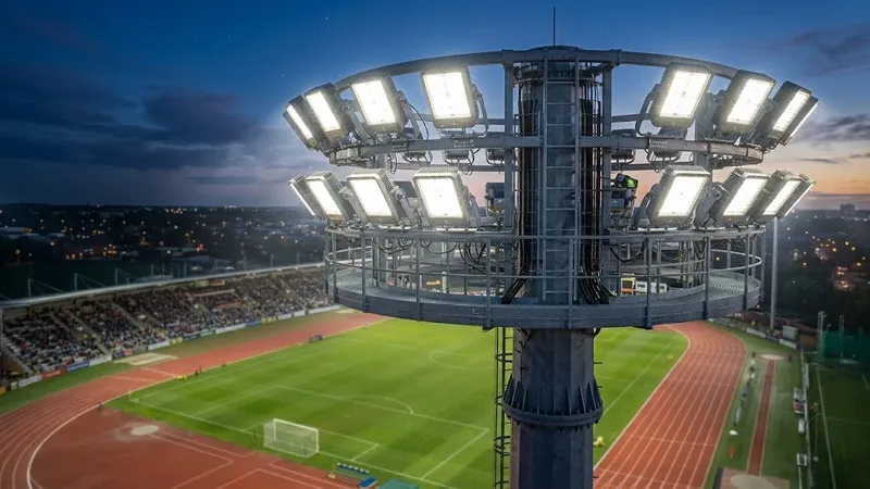
A reliable layout overlaps narrow, medium, and asymmetric beams around the oval. Long throws cover the opposite straight, while controlled medium beams fill near lanes and bends. Designers must also include the finish line, hurdle starts, relay changeovers, jumping runways, and the transition between the track and infield. More raw power cannot repair a poor distribution pattern.
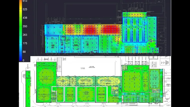
A verified photometric model should use the final pole coordinates, mounting heights, tilt angles, and IES or LDT files. The DIALux and AGi32 simulation guide describes the connection between calculation grids and field aiming. The team should also coordinate mast weight and effective projected area with the high-mast structural review.
4.Technical Comparison
These are design checks, not universal pass limits. Project targets depend on competition class, broadcast format, local regulations, and the governing standard. The CPS IES RP-6 overview is useful when a North American specification applies, while EN 12193 or national rules may control other projects.
5.Simulation and Field Commissioning
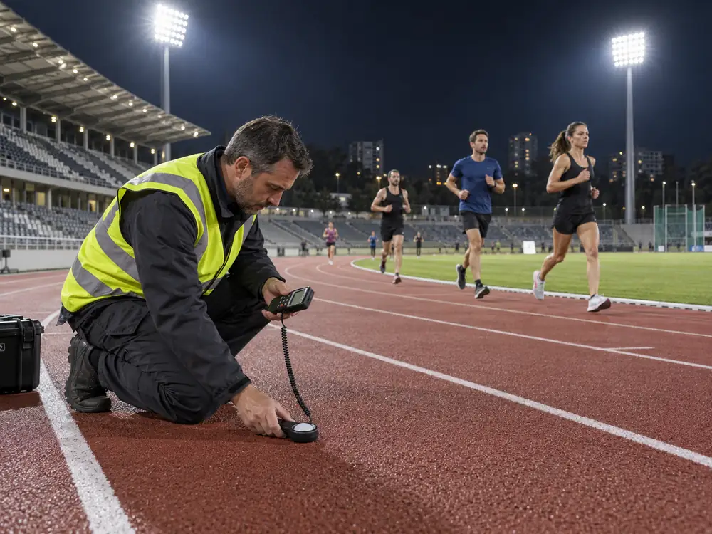
The commissioning team should first confirm product codes, optics, mounting heights, and every aiming angle. It should then measure the approved grids with calibrated instruments after the system reaches stable output. The report should include minimum, average, and maximum values, uniformity calculations, observer positions, weather conditions, supply voltage, and any field correction.
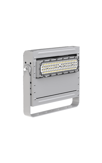
A visual walk-through remains necessary. Athletes should move through the critical routes while engineers inspect glare, shadows, and brightness transitions. Timing and broadcast teams should check the finish and camera views. Products such as the Megrez stadium floodlight or Dubhe Projection Light 1000W still require project-specific optics and aiming.
The final handover should preserve the calculation file, aiming schedule, measurement report, control scenes, and maintenance plan. Cleaning, fixture replacement, mast movement, and new scoreboards can change the original result. Periodic checks keep track and field lighting uniformity stable throughout the system life.