Contents
1.The Problem: A Golf Hole Is Not a Flat Lighting Plane
On a rolling golf hole, a bright tee does not guarantee a clear landing zone. A raised green changes the direction from the floodlight to the target. A ridge or tree canopy can obstruct that path. A clear ball-flight corridor and a readable landing area therefore need separate checks. Players also look along the hole from different heights, so their view of an exposed light source changes along the route.
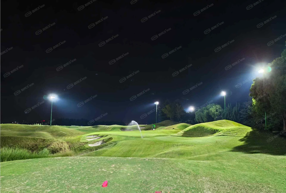
This makes golf course lighting a three-dimensional layout task. A plan drawing shows where a pole sits, but not the complete relationship between its optical centre, the ground and the player. The survey should locate both the target and anything blocking the light path. The CPS guide to night-golf ball tracking covers visibility; here, the focus is the surveyed geometry that supports it. Adding watts cannot remove an obstruction or correct a misplaced target.
2.The Comparison: Flat Assumptions vs Surveyed Geometry
That geometry affects more than a beam’s footprint. The inverse-square law and cosine law connect point illuminance with directional intensity, distance and incidence angle: E = I × cos θ ÷ r², under the point-source approximation. Terrain changes these inputs. The same beam can reach adjacent slopes at different distances and angles. A nominal beam angle alone cannot predict useful lux on a sloping surface.
Consider a teaching example with a luminaire 20 m above the datum and a target 40 m away horizontally. A target at datum level needs a downward direction of atan(20 ÷ 40) = 26.6° from horizontal. Raise the target by 5 m and the direction becomes atan(15 ÷ 40) = 20.6°. The difference is about 6.0°. The flat-model direction would pass below the raised target. These are not Suzhou pole heights or recommended mounting values.
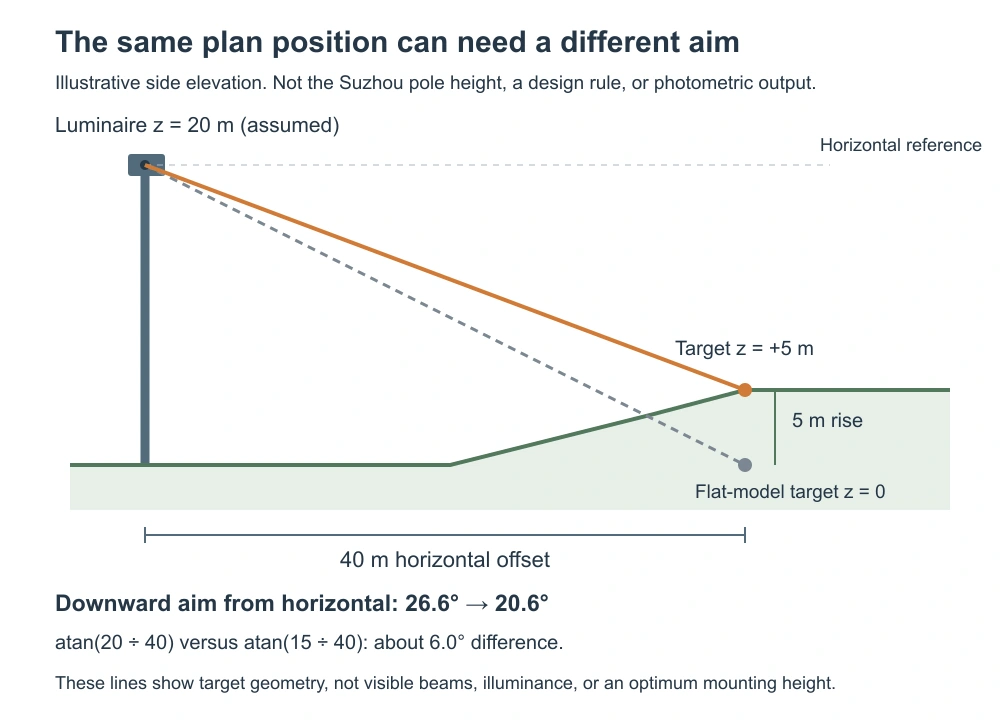
The diagram describes aiming geometry, not a calculated light level. Its downward aiming angle is different from θ, the incidence angle measured from the receiving surface’s normal. The aiming schedule should state its angle reference so installers can reproduce it. Actual lux also depends on the optic’s intensity in that direction and whether the path is clear. The comparison below identifies the modelling assumptions to check.
Concept-stage comparison, not pass/fail limits. Swipe sideways on narrow screens.
3.The Solution: Model, Aim and Check Each Playing Zone
Start the photometric model with a common elevation datum. Record pole-base levels, mounting heights, tee elevations, landing zones, greens, ridges and major obstructions. Equal pole lengths do not imply equal optical-centre elevations. A consistent coordinate system also makes later design revisions easier to trace. Use the selected luminaire’s exact IES/LDT file and coordinate the mounting and target positions before finalizing its optic.
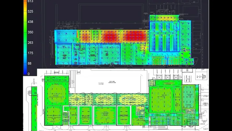
AGi32 documentation distinguishes surface-normal meters from fixed-orientation meters. A horizontal illuminance check over sloping land and a turf-normal check are not the same metric. Specify the required calculation plane and keep that definition during acceptance. Otherwise, the simulated value and site reading may describe different receiving planes. Inspect individual zones as well as overall averages, then review relevant player sightlines, aerial visibility and boundary receptors. CIE 150 provides obtrusive-light assessment guidance; applicable limits still depend on the site.
Turn the model into a fixture-ID schedule with mounting coordinates, target coordinates, pan, tilt and operating scene. The CPS aiming-error guide explains why small deviations matter. After installation, verify aiming and measure the agreed grids with calibrated equipment. Recheck weak zones after each correction, since redirecting one group can change coverage elsewhere. Record revised settings so the accepted layout can be restored after servicing. Keep tree-growth and maintenance access in the handover plan.
4.Case Insight: What the Suzhou Three-Hole Phase Shows
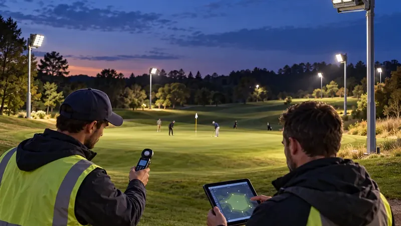
The CPS Suzhou project account describes lighting holes 7, 8 and 9 with 24 poles and 84 Sirius 1200W floodlights. It reports surveying the course, using optical simulation, aiming fixtures individually and checking illuminance by zone. This sequence links the surveyed geometry to the installed aiming positions and field checks. These details connect the design process to terrain and installation, rather than presenting fixture wattage as the whole solution.
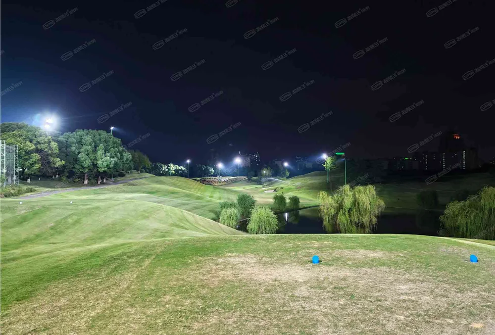
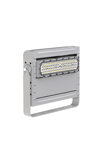
The rated luminaire total is 84 × 1.2 kW = 100.8 kW. This is arithmetic, not metered site demand or annual energy. The account gives no measured lux, uniformity ratio or glare score, and it does not establish the pole height used in the teaching diagram. These missing measurements limit performance comparisons, even though the equipment quantities are known. The Sirius 1200W product page identifies the equipment family; exact installed optics still require project records.
The useful lesson is to transfer the workflow, not the quantities. Three lit holes do not prove whole-course night-play coverage, and the totals do not imply equal allocation per hole. A further phase needs its own terrain, circulation, electrical and control review. Its aiming groups should follow the new playing zones, rather than repeat this allocation. For a new course, request a site-specific lighting design review with survey levels and intended use before copying another project’s pole count.
5.Technical Sources
Keywords: golf course lighting, golf lighting layout, terrain-aware lighting design, photometric simulation, floodlight aiming, elevation survey, fairway lighting, green lighting, illuminance uniformity, glare control.