Contents
1. Start With the Flight and Landing Task
2. Assess Apparent Size and Contrast
3. Coordinate Aiming With Player Sightlines
4. Keep Useful Coverage Inside the Brief
1.Start With the Flight and Landing Task
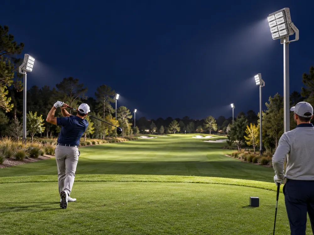
Consider a player following a drive after sunset. The tee looks bright, but the ball disappears as it rises beyond the nearest beam. It becomes visible again near a lit landing area. This illustrative check shows the gap between illuminating grass and supporting golf ball tracking. A lux reading on the tee cannot describe the whole visual task or guarantee continuous tracking.
The R&A Equipment Rules set a minimum ball diameter of 42.67 mm. That small target changes apparent size as it travels away from the player. The design brief must therefore define the occupied holes, likely flight corridors, viewing positions, and landing zones. Night golf lighting should connect those tasks, while keeping useful visibility separate from a claim that every shot will always remain visible.
2.Assess Apparent Size and Contrast
For a 42.67 mm ball, the small-angle estimate θ ≈ D/r gives the values below. D is ball diameter and r is viewing distance. These figures describe geometry, not a minimum visibility standard. Whether a player detects the ball also depends on its light exposure, background luminance, motion, weather, and the observer’s vision. A small target does not become reliably visible just because the fairway average increases.
The ball can pass in front of dark sky, trees, turf, or a bright luminaire. Its contrast changes through that sequence. Engineers should examine vertical illuminance and other relevant orientations at several heights within the flight corridor. Those planes support design analysis, but they are not a direct prediction of ball luminance. The photometric simulation guide introduces modelling inputs and verified optical files.
3.Coordinate Aiming With Player Sightlines
LED golf floodlights need a distribution that serves both the flight corridor and the landing surface. A narrow beam may reach far down the hole yet leave gaps beside it. A broad beam may cover nearby turf but place too much light outside the task area. Engineers should compare overlapping distributions and check the result from each active tee, rather than extend one beam setting across the course.
Direct source exposure can also reduce contrast when the player looks upward. CIE 112 limits its Glare Rating method to viewing directions below eye level, so a passing GR calculation does not certify high-ball tracking. The stadium glare review explains the mechanism. The pole-layout comparison adds mounting context, but its soccer arrangements are not prescribed golf coordinates.
4.Keep Useful Coverage Inside the Brief
A flight corridor is a three-dimensional task, but it is not permission to light the sky without limits. CIE 150 addresses the unwanted effects of outdoor lighting on surrounding environments. Designers should assess spill light, source intensity toward neighbours, and the approved operating hours alongside the player views. Sensitive trees, water edges, and nearby roads may change the feasible aiming envelope.
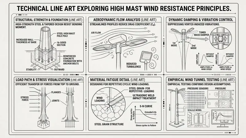
That envelope also affects the structure. Moving a pole outward or raising a headframe changes throw distance, luminaire loading, and service access. The high-mast structural guide describes the need to coordinate optics with the support system. Engineers should review terrain, mast movement, foundations, electrical routes, and maintenance before fixing the final aiming schedule.
5.Verify Tracking on the Installed Course
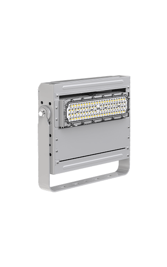
The CPS Dubhe Projection Light 1000W listing offers modular optics and an optional anti-glare hood. Designers should request photometric data for the exact selected version and shield configuration. The model must establish whether that equipment can serve the required corridor without exposing players to intense sources. A wattage, beam-angle label, or product rendering cannot prove that result.
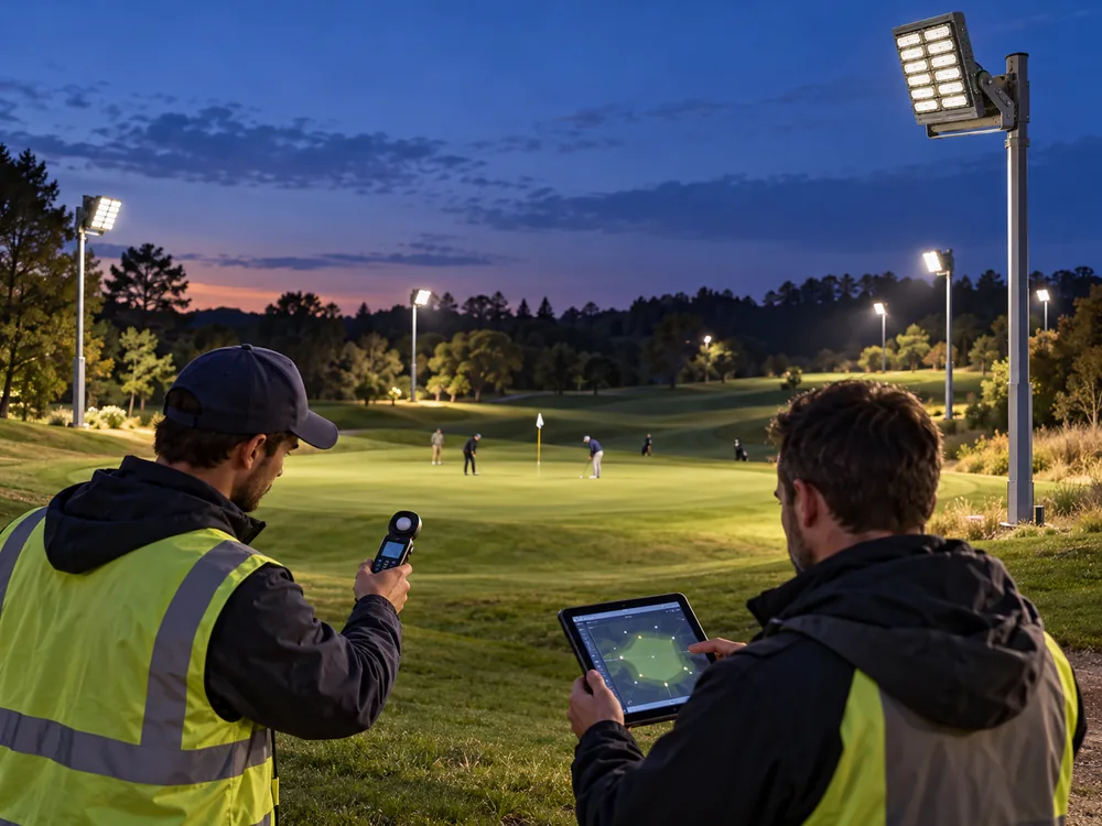
CPS describes four 18 m lifting poles and a ≥550 lx average-illuminance requirement in its Grade III high-pole football project. This is a soccer case, not a tested golf installation. Its relevant lesson is coordination between the brief, optics, and controls. Golf commissioning should combine calibrated surface measurements, recorded aiming angles, and repeatable shot-view checks from representative tees, with results retained for future adjustments.