Contents
1.Define the Receiving Plane Before Comparing Lux
A contractor receives two lighting reports for the same sports hall. Both use the same luminaires and show acceptable average lux, but the results differ. One grid sits on the court. The other sits 1.5 m above it. This illustrative review starts with the lighting calculation plane, because the reports describe different receiving positions before any equipment difference is considered.

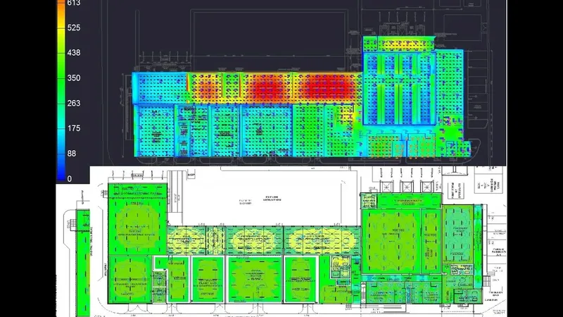
A calculation point needs a position and a receiving direction. A horizontal plane usually evaluates light arriving on a level surface. A vertical plane evaluates light on a standing surface facing a stated direction. The CPS guide to horizontal and vertical illuminance explains the practical distinction. Neither result can stand in for the other, and a lux value without its plane definition is incomplete.
2.Height Changes Distance, Beam Sampling and Shadows
Raising a grid changes its distance from each luminaire and the direction in which it samples the intensity distribution. It can also move points above an obstruction or into another part of a narrow beam. For an assumed point source directly overhead, a 10 m separation becomes 8.5 m when the plane rises 1.5 m. With unchanged axial intensity and no reflections, direct illuminance rises by (10 ÷ 8.5)², or about 38%.
That example is not a prediction for an entire court. Real layouts combine several sources, off-axis intensities, reflections and obstructions. Some points may rise while others fall, so minimum illuminance and uniformity can change differently from the average. In a DIALux or AGi32 simulation, compare height revisions with every other input fixed. Do not select a convenient raised plane simply because its results look better.
3.Direction Changes What the Sensor Receives
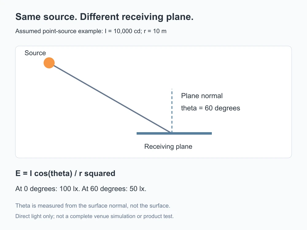
For one direct point-source contribution, illuminance follows E = I cos θ ÷ r². I is intensity toward the point in candela, r is distance in metres, and θ is the angle between the incoming direction and the receiving surface normal. With assumed I = 10,000 cd and r = 10 m, normal incidence gives 100 lx. At θ = 60°, the same contribution gives 50 lx.
Rotating a vertical receiving direction can therefore change a result even when the point stays at the same coordinates. Camera-facing and opposite-facing values must retain their direction labels. A grid's geometric position alone does not establish the software meter orientation. AGi32 distinguishes grid placement from meter types. This is also separate from floodlight aiming, which changes how the luminaire sends light rather than how the calculation point receives it.
4.Record Height, Normal and Grid Settings Together
The following examples describe settings to document, not universal compliance heights. The applicable sport, competition level, camera plan and assessment procedure must set the required measurement planes. A default workplane can be useful during modelling, but a designer must replace or confirm it before issuing a compliance report. On sloping ground, define whether heights follow the local surface or a common project datum.
The lighting calculation report should state plane names, coordinates or extents, elevation reference, normal direction, grid spacing, calculation method and operating scene. Keep maintenance assumptions and photometric revisions traceable too. When comparing options such as the Dubhe 1000W floodlight, hold these settings constant; product wattage cannot correct a mismatch in the assessment basis.
5.Carry the Same Plane Into Site Measurement
The CPS Grade III high-pole football project reports four 18 m lifting poles and average illuminance above 550 lx after commissioning. That published result illustrates the value of checking the installed system. The page does not provide every calculation-plane setting, so its average should not be transferred to another plane or used to predict camera-facing vertical light. A project claim needs its own measurement basis.
Before commissioning, export a point schedule with coordinates, heights and sensor directions. On site, place a calibrated sensor at those positions, keep people from shading it, and record the operating scene and relevant ambient conditions. Investigate plane or orientation errors before changing aiming or adding luminaires. A reproducible lighting simulation connects the model, report and field measurement through the same receiving geometry.
6.Technical Sources
Keywords: lighting calculation plane, calculation plane height, horizontal illuminance, vertical illuminance, sensor orientation, lighting simulation, calculation grid.